Welcome to ! +86-755-26975359
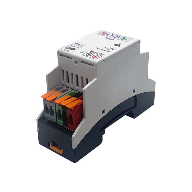
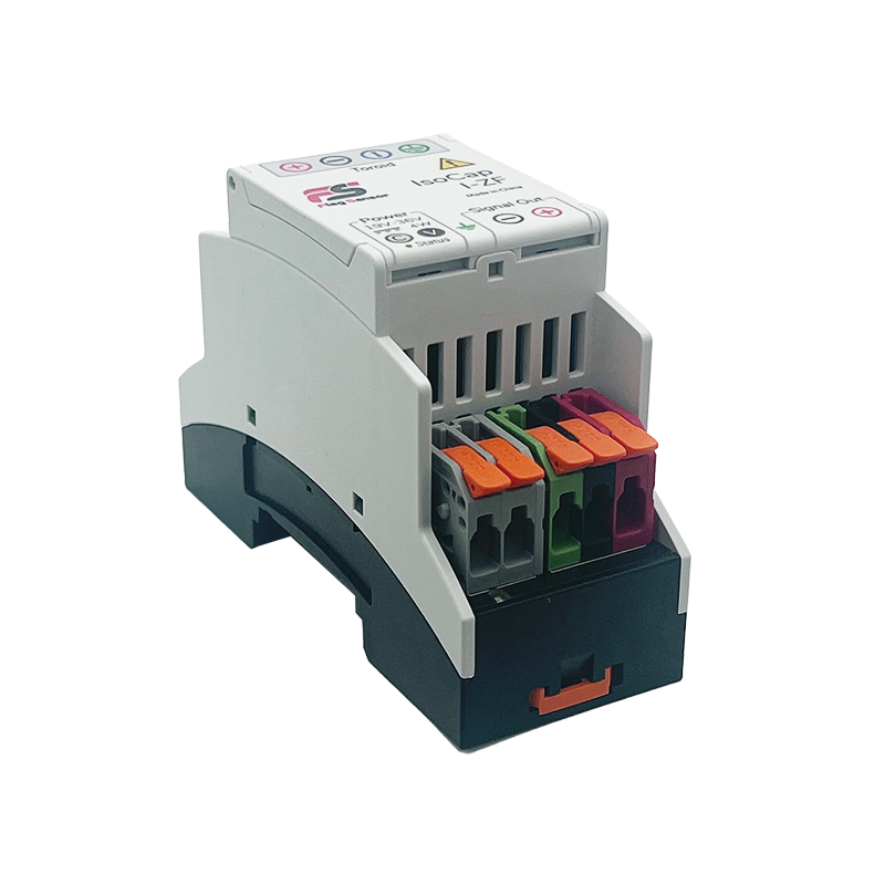
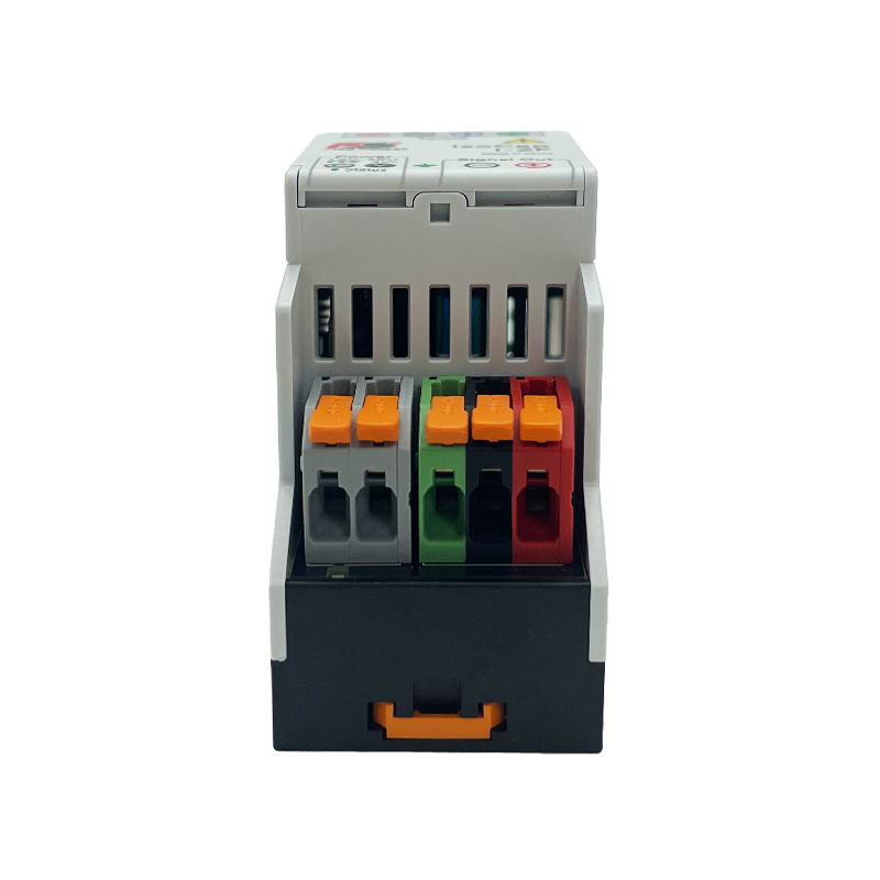
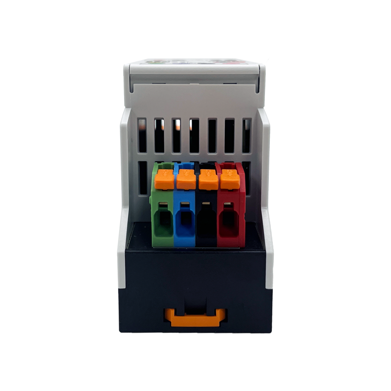
The IsoCap I-ZF input connector is located at the top of the module in the figure bellow. A connector that servers to power the sensing unit, output signal and ground the sensor lay along the bottom.
| IsoCap I-ZF | 20 A | 50 A | 100 A | 200 A | 300 A | 500 A | 600 A | 1000 A | 2000 A |
| Bandwidth ( - 3 dB point) | DC - 100 kHz | DC - 80 kHz | DC - 60 kHz | DC - 50 kHz | |||||
| Power consumption @ 24 V | 200 mA | 300 mA | 600 mA | ||||||
| Accuracy | ± ( 0.1 % of reading + 0.005 % range) ± ( 0.02 % of reading + 0.005 % range) |
| Max Input delay | < 1 μs |
| Max total phase shift at 60 Hz | < 0.01° |
| Isolation voltage | 5 kV for 1 min |
| Isolation voltage for transient | 10 kV for 50 μs |
| Insulation Resistance | > 500 MOhm ( @ 500 V ) |
| Thermal drift gain | < ± 0.01 % / °C |
| Operating temperature | – 25 to 70 °C |
| Storage temperature | – 40 to 80 °C |
| Mounting Type | DIN Rail and Panel |
| Outer Dimensions | 3.5” x 2.5” x 1.4” |
| Weight | 77.8 g ( 2.75 oz ) |
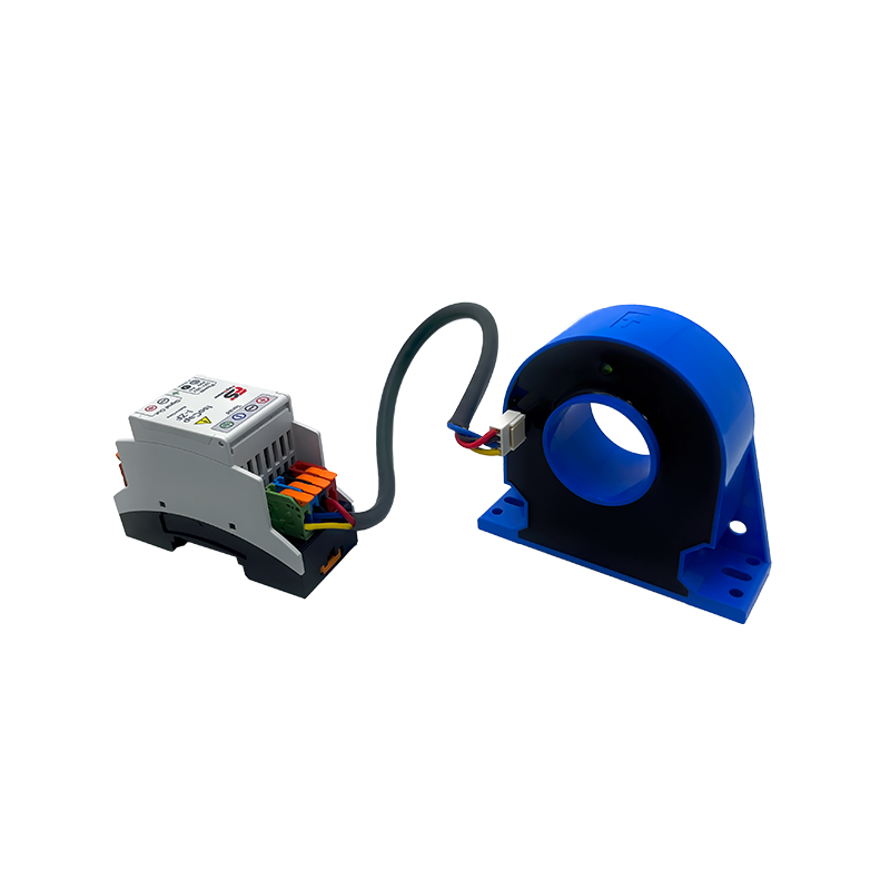
The IsoCap I-ZF is a single channel module designed for high-quality high current measurements in the range from 20 to 2000 Amperes. The IsoCap I-ZF is a combination of two units: (1) sense the current flowing through a conductor and (2) convert the signal into a standard ±10V . The compact form factor of the IsoCap I-ZF module set allows users to setup high channel density monitoring systems, making it ideal for high performance compact systems.
| Input-Output non-linearity | < 0.02 % or < 0.005 % |
| Max total phase shift at 50 Hz | < 0.01° |
| Max Input delay | < 1 μs |
| Isolation voltage | 5 kV for 1 min |
| Isolation voltage for transient | ± 5000 V |
| Insulation Resistance | > 500 MOhm ( @ 500 V ) |

- Connect external power source to power the unit. For proper functioning the power supply should provide a voltage as specified with at least 0.2 A of continuous current and 0.4 A surge during module start-up.
- Pass conductor through aperture and observe orientation for proper signal polarity.
- Securely connect one end of a 4 wire cable with corresponding connectors to IsoCap I-ZF main unit, and the other end to the inputs of the sensing unit.
 Simplified Chinese